- Inicio
- >
- NOTICIAS
- >
- Industry News
- >
- How is the photoelectric encoder used in the measuring instrument?
How is the photoelectric encoder used in the measuring instrument?
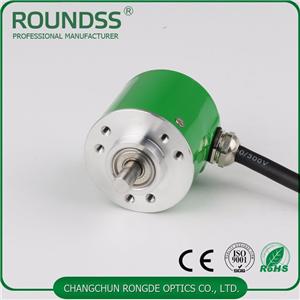
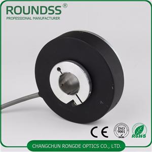
A photoelectric encoder is a sensor that converts mechanical displacements on an output shaft into pulses or digital quantities by photoelectric conversion. This is the most used sensor at the time, and the photoelectric encoder consists of a grating disk and a photoelectric detection device. Encoders are available in optical, magnetic, inductive and capacitive. According to its scale method and signal output mode, it can be divided into three types: incremental, positive and hybrid.
The use of photoelectric encoders in gravity measuring instruments
The rotary photoelectric encoder is used, and its rotating shaft is connected with the compensation knob shaft of the gravity measuring instrument. The angular displacement of the offset knob in the gravity measuring instrument is converted into a certain amount of telecommunication quantity; the rotary photoelectric encoder is divided into two types, a positive encoder and an incremental encoder.
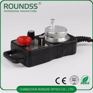
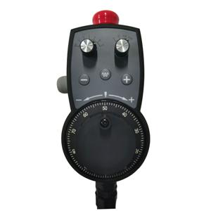
The incremental encoder is a pulse-output sensor whose code wheel is much simpler and has a higher resolution than a positive encoder (electronic handwheel). Generally, only three code channels are needed. The code channel here does not have the meaning of the positive encoder code channel in practice, but the episode count pulse. The outer track and the center track of its code wheel have a number of uniformly distributed light-transmissive and opaque sectors (gratings), but the two sectors are offset from each other by half a zone. When the code wheel is changed, its output signal is the A-phase and B-phase pulse signals with a phase difference of 90° and the pulse signal generated by the third code channel of a light-transmissive slit (which serves as the reference orientation of the code wheel, An initial zero signal is supplied to the counting system). The phase relationship (leading or lag) of the two output signals A and B can determine the direction of rotation. When the code wheel is rotating forward, the A-channel pulse waveform is π/2 ahead of the B-channel, and when it is rotated, the A-channel pulse is delayed by π/2 from the B-channel. In the practical circuit, the positive edge of the single-stationary wave is triggered by the lower edge of the A-shaped shaping wave, and the positive pulse of the B-shaped shaping wave is 'AND'. When the code wheel is rotating forward, only the forward port pulse is output, and conversely, as long as the reverse port pulse is output. Thus, the incremental encoder determines the direction of the encoder's transition and the relative angular displacement based on the output pulse source and pulse count.
Generally, if the encoder has N (code channel) output signals, the phase difference is π/N, and the countable pulse is 2N times the number of rasters, and now N=2. The drawback of the circuit is that sometimes a missed pulse is formed into an error. This situation occurs when one signal is at a 'high' or 'low' level while the other signal is between 'high' and 'low'. Reciprocating changes the situation, at this moment, although the disc is not displaced, it will attack the output pulse in one direction. For example, when the dial is vibrating or manually aligned.
For more information on encoder products, please contact Changchun Rongde Optical Co., Ltd.


